Saturday, February 17, 2024

Timonium Train Show, in a few pictures

I wanted to share a couple of shots with the audience from the train show in Timonium, MD, the first weekend of February.

I had to do a bit of shopping, and after I finished, I took my camera through a bunch of the layouts and took some photos of things that struck my fancy.

Enjoy!


This would have been better with a tripod and a different lens.. And yes, that bridge is VERY long.

PRR style signals and catenary. Looks great!

RF&P Car spotted!

An RF&P wide nose unit? Sign me up!

I just wish this wasn't under the coaling tower!

More photos can be found in the gallery at richmond-terminal.org


Thursday, February 15, 2024

Adding an Interchange

 A suggestion from one of the usual suspects around Christmas time was to add an interchange track in Acca to add another "universal industry" to the railroad.

Long time readers and operators will remember that version 1 of the Richmond Terminal had a Norfolk Southern interchange south of Acca off the mainline.

Since the tail of the drill track wasn't being used much at all, I figured would could use that as a base and proceed from that point.

I dropped in a curved turnout recovered from the previous layout to give an additional industry track, or be used as a deconflict between the drill and new interchange track.


A couple pieces of flex carried me around the corner.


When I decide to complete the Acca Wye, this track will need to be removed, but with the fact that I do not have a timeframe on that currently, this makes a bunch of sense to add, operationally.


And done. I made a custom bumper out of some foam sheet I had laying around.


I didn't realize that I didn't complete the DCC wiring until this last op session, but I have already fixed that.

A few more pictures can be found in the gallery on richmond-terminal.org

Tuesday, February 13, 2024

Resistor Axles, Tank Cars and working around all the different truck designs

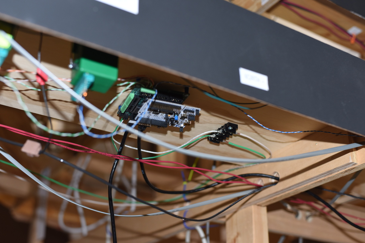
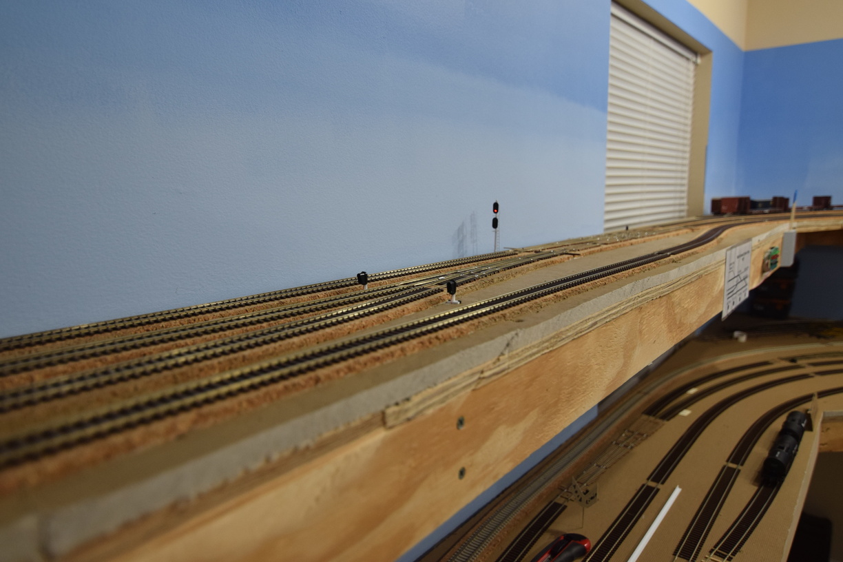
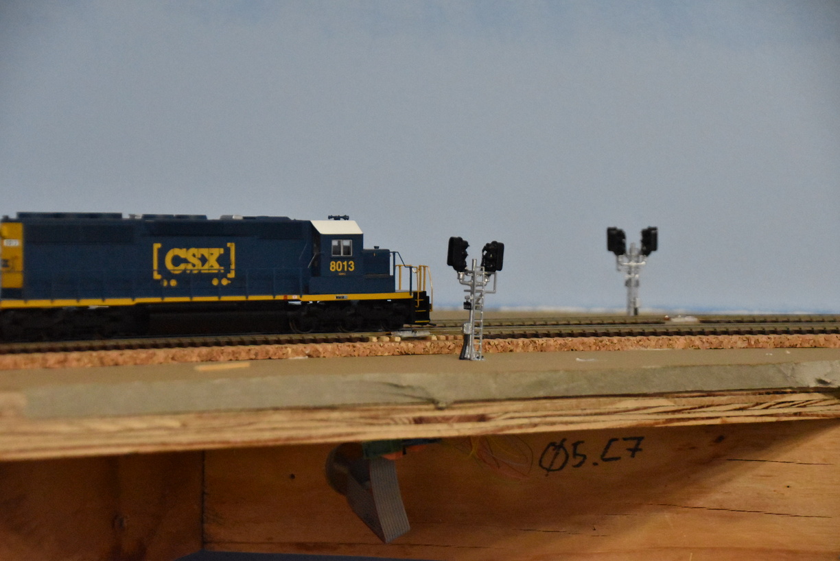
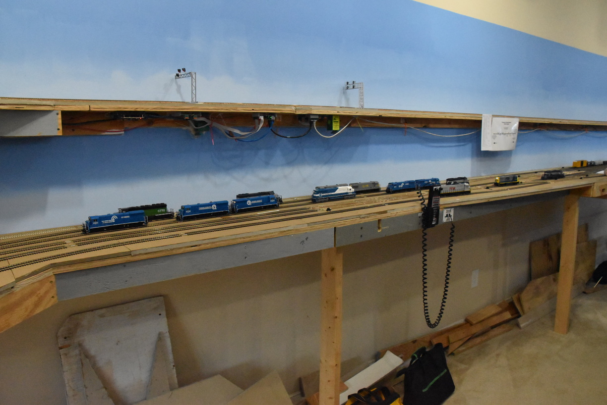
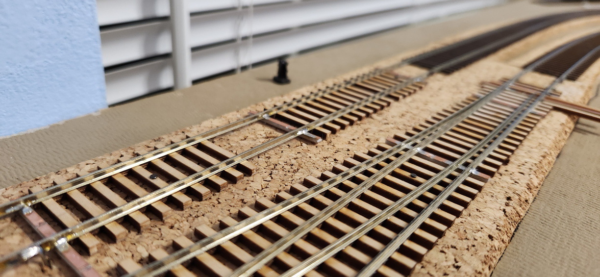
As my long term readers and any operators of the Richmond Terminal know, the layout is signaled.

How it works is based on the system being able to detect that something - a engine, a passenger car, a freight car, an entire train - is in a block of track. Since I am using DCC, the easiest way to figure out if something is there, is by measuring that there is some amount of current draw.

Engines are easy, as they draw power, even when they aren't moving since the decoder does need a bit of power no matter what (sound decoder or not). For passenger cars, if they are lighted, again easy.

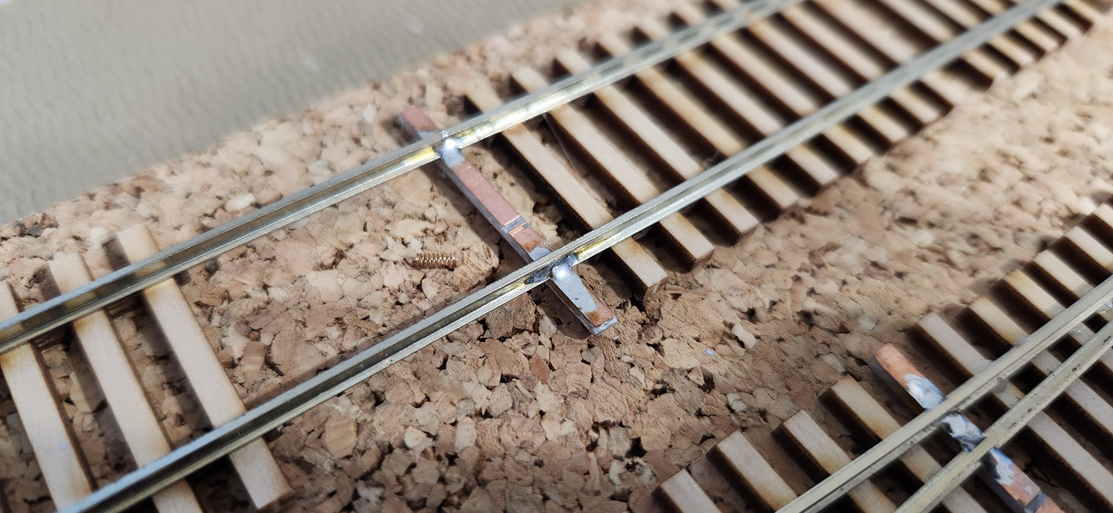
For your standard freight car, they don't draw any power, so that's a problem.

As my rolling stock is standardized on metal wheelsets, I have made a bunch of resistor wheelsets, where I glue a small surface mount resistor and then use conductive ink or paint to make a circuit. You can take a look at a prior blog post where I talk about making a batch of resistor wheelsets here. I fixed the resistor size - they are actually 1206 size SMT resistors. 10K Ohm, 1/8 watt - on that post when I realized I erred.

My standard replacement axle is Intermountain. They sell the axles in bulk packs of 100. They fit in a wide variety of truck designs, but for some truck designs, they do not fit correctly.

As an alternative, especially for cars that the factor axles are plastic, while the wheels themselves are metal, I glue the resistor in the middle of the axle, and then connect each side to the wheel with conductive paint.

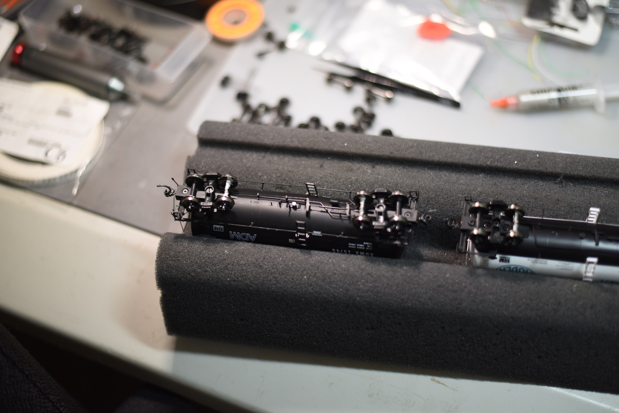
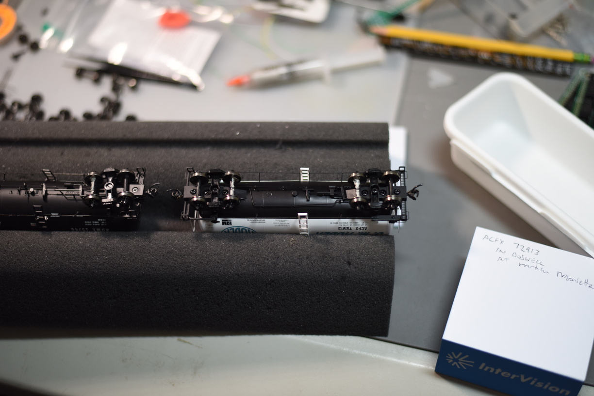
It seems that tank cars are a consistent issue with being incompatible with the Intermountain option.

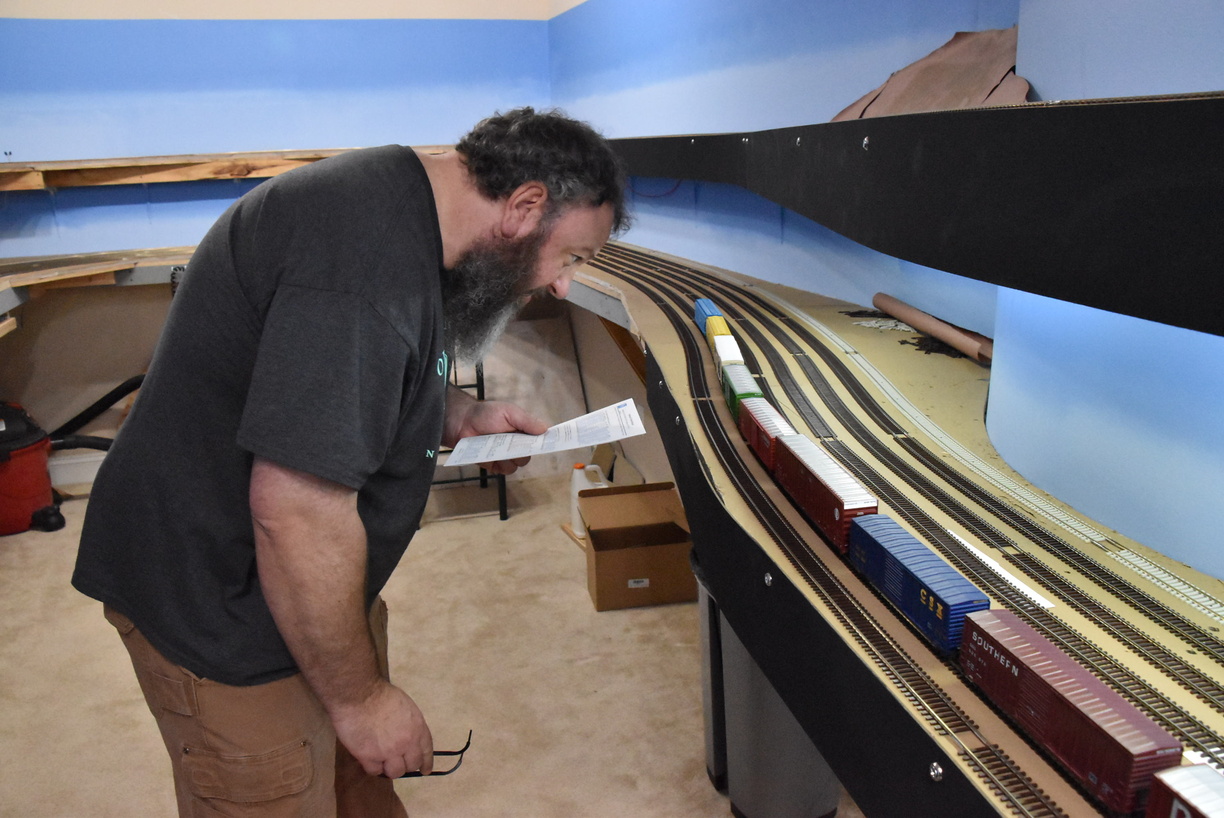
I have been checking the tank cars and also spotting any without Kadee couplers installed, so I grab them for the coupler replacement, and take the opportunity to handle the resistor wheelset issue.


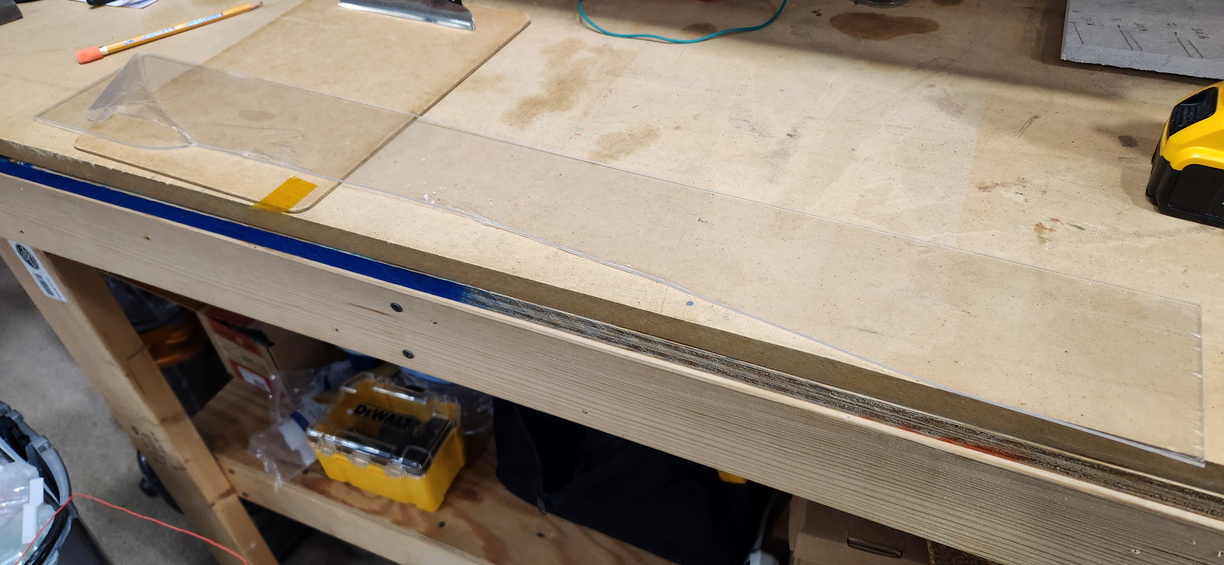
The paint does take a bit to try, so doing this can tie up the foam cradle for a day.

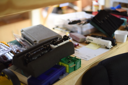
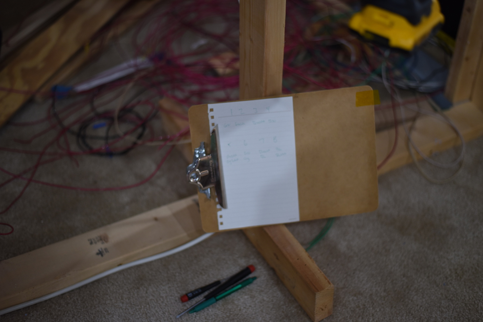
Cradle off the bench so I can do something else.


Sunday, February 11, 2024

A Retrofit

Had to pull this LCC node out, and add a terminal block to feed it DC power, as this leg of the LCC network was having some power issues, causing the last node in the chain to brownout and stop responding.

Thankfully, I have a 12V DC bus already placed around the layout, so I just had to pull wire, solder some spades on, install a terminal strip, and then wire to the node. About an hour's worth of work.

Green and White 14AWG wire is the 12V DC bus; red and black 12AWG is my DCC bus. Cat5 is LCC bus, in this shot. The gray cable is Digitrax Loconet.


It's a bit tough to see, but I had to write down the colors of wire from the tortoises to the nucleo node.


Friday, February 9, 2024

Dwarfs in Glen Allen

 Built two dwarfs, using Atlas heads; used one Tomar head.

These signals are controlled by a Nucleo, so the signal head driver is a combo of a logical signal head inside JMRI, and a Nucleo DevKit under the layout.


Tuesday, February 6, 2024

A few words about switch machines..

 As I assume most readers know, my turnouts that aren't manually controlled by Caboose Industries ground throws (mostly in Acca, with a few others here and there), are thrown by Tortoise machines from Circuitron.

The Tortoise is probably one of, if not the most, well known "slow motion" switch machine in the hobby. The green case is instantly recognizable.

There hasn't been any competitors with similar footprints and motion that have had what I would call significant success in the market. There have been options, certainly, and one of those is the Cobalt machine.

I bought one to try some years ago. I installed it on a turnout in Brooke that goes to the E&P interchange, as at the time, I did not have any more Tortoises available to install, and it felt like a great time to try it, as the area where it needed to be installed has a bunch of DCC bus wire, LCC cables and other assorted stuff in the physical space.

After a couple of months and 4 or so sessions, I can report that you should save your money.

Yes, the cobalt is smaller. Yes, making the connection is super easy with the spring loaded connector.

But it isn't as powerful, and it is too slow to respond, causing your operators to hit the button multiple times, making it appear to be broken.

Maybe as a semaphore driver, it would be better. I don't know. This one is free to a good home.

Cobalt out, Tortoise in.


Saturday, February 3, 2024

Lighting Follow Up

 This is a short follow up to my original underdeck lighting post here. As I was reworking the block detection, I had to move the LED lighting around a bit, and took the opportunity to take another picture.

This is a great example of how I used the aluminium L bracket, and stuck the LED strips to it, and then bridged from one strip to another.

The yellow tape  at the end closest to the camera is kapton tape. Very handy for stuff like this, as well as decoder installs, etc.


I buy the channel in 8' lengths, generally, and cut it to size with a hacksaw. You can see this has the factory barrel connector end at one side.


Thursday, February 1, 2024

Tidying Up

 Got tired of looking at it, so out came the white glue and a acid brush.


Maybe there will be paint and grass and trees at some point..

Wednesday, January 31, 2024

Signal Reworking

One of the outcomes when you operate is learning what changes need to be made to the layout to make operations smoother, more realistic, etc.

The railroad is maturing, which is giving me a chance to go back and install signals in areas that haven't been a priority, or to rework an area where the original signal install isn't reflective of how that area should be setup.

One of these locations that needed a net new install is the industrial turnout in Greendale, between the GN control point, and the Glen Allen (GA) control point.

There is a fair amount of industrial spots in this area, and both main lines have turnouts in place. I needed dwarf signals to protect these turnouts. One of them is currently manually thrown with a ground throw, so that will need to be modified to be thrown via a switch machine first, before signals get installed.

For the turnout that is currently controlled by a button (and will be controlled by the dispatcher in the future), I built a coulple of dwarfs and installed them.


I also took this opportunity to cut away a bunch of cork roadbed, and make the area look more realistic from a lineside perspective.

I had planned for a set of intermediate (repeater) signals between North Doswell and South Milford. This is matched up with Rutherglen on the prototype.

These are NJ International signals, with snow hoods. I will need to put something on the fascia in this area, since it can be hard to see these from the aisleway.


A spot that needed to be reworked is inside Doswell towards the north end.

At the turnout that branches into track 4 from track 3, I originally had 2 high signals in this area. As I needed to only protect the turnout state, and not give advancement permission, I built and installed two dwarfs in their place.

The high signal in the background is for traffic that will be using the crossover, northbound, and getting clearance to enter the RF&P mainline


More pictures can be found in the gallery at richmond-terminal.org

Tuesday, January 30, 2024

January Operations - A Famous Photographer Visits

 During the January operating session, the Richmond Terminal hosted a (in)famous model railroad photographer, Wayland Moore.

Your layout host is always busy during a session and finds it difficult to take a bunch of quality photos, but having a visiting shutterbug was amazing.

Here are but a sampling of shots from Wayland.

Engineer Dan Moore inspects his train at North Acca prior to departure, looking to make sure his paperwork matches.

It would be impossible to show all the great shots he took without making this blog entry extremely long, so I will pick a couple that stood out to me.


Road freight goes by the new Intermediate signal installation at Rutherglen. Photo by Wayland Moore.

I appreciate that many of the shots showed trains going by signals. Management puts a significant amount of effort into the signalling system.


Traffic manager discusses the yard at the start of the session.

A shot that never occurred to me - the ready engine tracks.


A highlight for many that I've never captured - the food!

The crew debriefs after the session, while enjoying desert.

More photos from O. Wayland Moore can be found at richmond-terminal.org

Monday, January 29, 2024

January Op Session

The January 2024 Operating Session is in the books.

One major failure occurred, a single rear end collision. Many HO scale passengers were injured when their cars rolled over.


The engineer didn't seem upset.


Root cause was determined to be a signalling system failure where a clear aspect was given due to a occupied block not being checked.

A tragedy, and management regrets the incident.

Besides the one lamentable incident, the session proceeded well. All trains were run and a good time was enjoyed by all.


Keep your eyes open for the next session invite for February 2024.

More photos can be found at richmond-terminal.org

Monday, January 8, 2024

Reworking Block Detection for Signals

The Richmond Terminal is a signaled railroad. The end goal is to have a functional CTC system in place like version 1 did. Version 1 used a virtual CTC panel based on the Union Switch and Signal components inside JMRI.

As we are still working on the operating scheme, I decided that an Automatic Block System (ABS) would make the most sense to implement at the start and once the operating scheme was solidified, I would pivot to setting up the CTC system.

ABS is currently running based on the LogixNG inside JMRI. As I have worked through the configuration, I realized that when I connected the track blocks, I erred.

The Richmond Terminal is a 2 track mainline railroad, which means there are crossover from one track to another. These crossovers are frequent. The railroad is just shy of 10 scale miles; there are 14 crossovers total.

I setup 1 detection section per crossover. This meant a couple of things - detection of the crossover section would prevent a dispatcher from throwing one under a train, but the detection state would not help me drop to red until a train moved through the crossover and hit the next block, and I could not test the crossover occupancy to set a signal aspect, either. 

Consider this example - a train is southbound on track 3, approaching a crossover. On track 2, a northbound train is moving through a crossover section, on a straight route. The crossover shows occupied, which is true for track 2, but NOT track 3.

This meant that I needed to go back and break apart the detection for each crossover and connect my blocks so that each component turnout of the crossover was detected separately.

I took advantage of this and did some rationalization of my DCC bus as well.


That's wire I pulled out from a part of 1 peninsula...

Here is a shot where I shortened bus wire and soldered new ends on. Had to clamp up a piece of plywood to give myself a working surface.


More pictures are in the gallery at richmond-terminal.org

Saturday, January 6, 2024

Protecting the fragile stuff

I daresay that almost every layout builder puts significant time and energy into their layout.

It's a downer when a scratchbuilt structure takes an inadvertent hit from a misplaced elbow or when an arm that is cleaning track, mashes a signal over.

In an effort to protect these installations on the layout, I've used Acrylic sheets that I've cut to size as guards.

I'm still (re-) learning how to work with this stuff, and mistakes can happen.


Whoops. Needed a bunch more scribes on that one.

Thursday, January 4, 2024

Car-nage In Pictures

What's that?


If you said "Kadee coupler spring", you're a winner!