Friday, April 17, 2020

LCC Nucleo DevKit Build Shots

Just a couple of in progress build shots from the workbench when I was putting together the first run of these.

The design is a mix of SMT and through hole with many key components having an option one way or another.

I've standardized on SMT for the CAN and power ICs as well as most of the standard passives. Diodes are TH.

Note the tweezers!

Thursday, April 16, 2020

Layout Control Options - The Main Problem

Layout control is a subject with an interesting history and there have been various systems and schemas that have ebbed and flowed in popularity over the years.

When I say layout control, I'm talking about an accessory bus or network and not something whose purpose is to allow you to make your engine move, so let's agree to call those train control for the purposes of these discussions.

Up until this point, most of the layout control systems were an additional use case driven by the need to connect throttles to the DCC command station, but all of these suffer from various architectural deficiencies. The sole exception to the offshoot situation that I can think of is C/MRI - Computer / Model Railroad Interface invented by Dr. Bruce Chubb. C/MRI has been around for a long time and has a pretty solid community around it; in fact many of the CTC systems that I know about use C/MRI as the infrastructure, whether the panel is driven from JMRI or a physical panel.

Various Arduino and other microprocessor based systems have been brewed and used, as model railroader are ingenious in their abilities to adapt things to model railroad use, going back to dyed sawdust as ground cover at the dawn of the hobby.

What these solutions have in common is a single, central problem.

Lack of Sustainability.

They are either the work of a single person (the Arduino schemes are examples) or company (Digitrax, C/MRI, Atlas, Walthers, etc) and in most cases, are closed and proprietary. So once the manufacturer stops making that or goes out of business, you either have to reverse engineer it and potentially run afoul of patents and the like or be willing to run it until it dies and throw it away to start over once you have enough failures that you can't live with it anymore. Similar story if the kids move out and you get that extra space to expand the pike but you can't buy that anymore.

Enter Layout Command Control.

LCC solves the problem, as it is a royalty free and license unencumbered standard that manufacturers are free to implement however they see fit. If a DIY type approach is more to your liking, the standards are available to you so you can work from that angle.

LCC is the adopted standards from the work of the OpenLCB group. OpenLCB was started from what I will call the ashes of the NMRANet project. If one wants to burn a day or three, you can search and find various electrons inconvenienced about NMRANet and how it went a bit pear shaped.

I first saw OpenLCB (still referred to as NMRANet) in 2012 at the Grand Rapids convention. I got an early DevKit, thinking that it would be something somewhat shake and bake. I was so so wrong.

Thankfully, that was then and this is now.

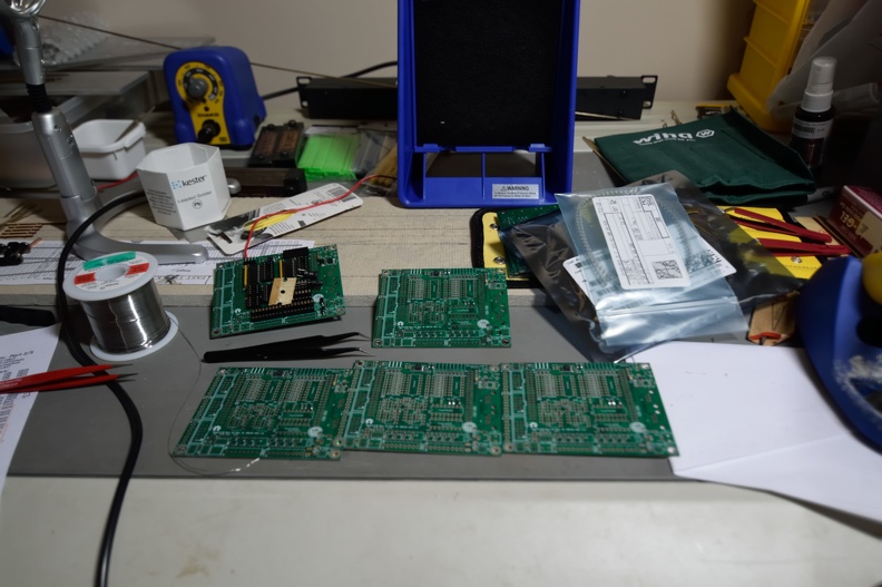
At this point, commercial hardware is available from RR-Cirkits and there are various open source DIY stuff too. I have a mix of RR-Cirkits and the Nucleo DevKit here on the layout. I personally laid out an expansion board for the Nucleo DevKit.

If you check out the main openlcb.org website you can see the general status. There is even a print book out about LCC!

I will put up more posts as I have time and inclination - this post has sat in a draft status for almost 2 years; its original post date was October 2018...

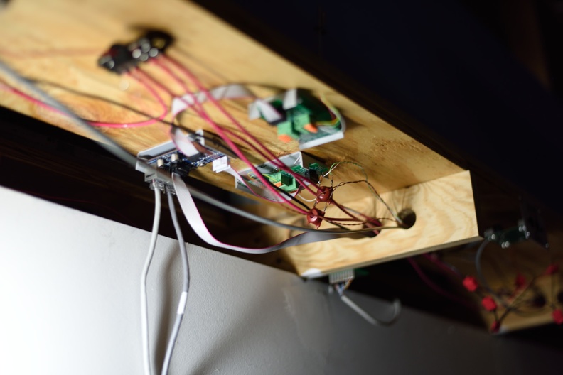
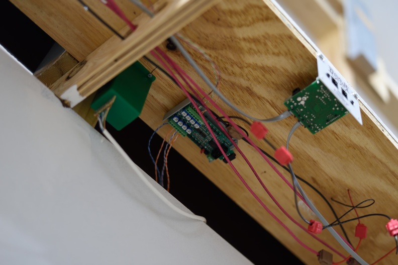
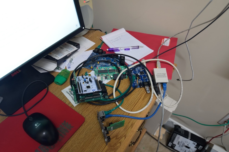
From 6 o'clock clockwise: (on edge) RR-Cirkits Tower-LCC, Nucleo DevKit (green and white PCB combo), Railstars IO (Blue PCB), LCC-Buffer. At center is a TCH Technology USB-Serial to CAN adapter that ended up having a fairly serious hardware bug..


Tuesday, April 14, 2020

Helix Completed

Long time Richmond Terminal operators remember that the old layout had two helixes, stacked on top of each other.

One was 11" and the other was 15" high.

On the new layout, I needed a helix that was 16" or so high.

The two individual structures donated enough parts to get the new helix built.

The spacers were replaced with clear 1x2 and 1x3 pine and glued with the same construction adhesive used to glue down cork.

These pictures don't show track being complete, but as I write this blog post, track has been completed over this area.

You can see the last piece of sub-roadbed hasn't been placed here.
A bridge had to be built, just like last time on the small helix. Also note the plywood cut back to give clearance to the tier below.
More pictures are on the website gallery at richmond-terminal.org

Saturday, April 11, 2020

Electronics Teaser

Quick teaser shot of upcoming blog posts.

In this shot there are 4.5 different projects in various phases of completion.

I got tired of putting stuff in boxes and taking it on and off the work bench so I found some scrap 1x3 and 1x4 to make some circuit board holders.

Used the table saw with the blade set at a 15 degree angle and just cut by eye. Worked pretty great.


Wednesday, April 8, 2020

Flash Traffic from Richmond Terminal Headquarters - Signal Activation

This evening at approximately 22:45 Eastern, 02:45 Zulu, the first signal on the Richmond Terminal Railroad was wired, tested, and activated on the control system.

This signal protects the siding and main track 2 for Southbound traffic at Milford, VA.

The Management, Officers and Employees of the Richmond Terminal are rightfully proud of this occasion and pray you lift a glass in celebration with them. (once you have gone off your current tour of duty, of course).

Tomar 3/3 US&S Signal installed alongside Main 2
In the background, you can see additional signals awaiting installation. The Signaling department will continue to work in the Milford area, including the South Milford control points before moving north towards XR, Hamilton and the Quantico CP.

Hamilton Signals Installed

Signals at the Hamilton Control Point have been installed and connected to the various driving boards.

I've got some additional updates around signals on the way so look for that content to post fairly soon. Being stuck at home is helping move the layout forward.

Here is my favorite shot:

Looking North here

Under the layout to drive this stuff, I have RR-Cirkits Fan out boards (FOB) and a Signal-LCC board that drives the signals. The FOB lets me go from the fine 30 AWG gauge wire on the signals to the .1" square header pins.

Signal LCC at center left, FOBs center and center-right.

Working through the FOB lead me to put together an alternative circuit design to make it more economical, from both a money and space perspective. A future post coming about that as well.

Tuesday, April 7, 2020

Bridge Update and Spot the Error

Permanent track installation on Bridge #1 has been done.

This bridge carries 3 tracks over the room entrance at a high that makes this a cross between a nod under and a duck under as there is about 50" or so of clearance from the floor to the underside.

At the joint between bridge and permanent benchwork, I soldered PCB ties in place to help fix the rail in place to prevent any movement that would cause the track to misalign, making derailments and other operational issues a possibility.

Once soldered and secured, I used a cutoff disk in the Dremel to cut the rail.

It mostly worked and I got in a hurry with the soldering process, and used the gun instead of the iron.

So, take a look at this picture and see if you can spot the error.


If you said, on the track nearest the camera, those PCB ties look destroyed, you'd be right.

Sigh.

I had to rip that apart and redo it totally since the ties would not hold the rail in gauge anymore since they'd been delaminated by the high heat from the soldering gun.

Sunday, April 5, 2020

Doswell and North End Staging Benchwork, Re-Work

As mentioned in a previous post on the blog here, the area of the layout that hosts South Doswell as well as the entrance/exit to the north end staging yard, required a rework.

The area was torn down to benchwork and new plywood subroad installed.


This also gave me a chance to use larger pieces of homasote, reducing the number of joints in play.

New homasote down.
All things considered, this wasn't all that bad of a job to do. I wish I would haven't had to do it, but that's water under the bridge.

Painted and ready for roadbed.


Saturday, April 4, 2020

Block Detection

Quick block detection shot to share with my readers.


What you are seeing here at the center of the shot is a RR-Cirkits BOD-8 board. This is a board made to detect occupancy of up to 8 blocks, using current transformer coils that get placed on the DCC feeder for a rail of your choice. Also in the picture - Tortoise switch machine and Digitrax UP5 panel.

You can see that I use red for DCC Rail A and Black for DCC Rail B as the DCC bus and use 3M suitcase connectors to go from bus to feeder gang to feeder.

Per detected block, this is a probably the cheapest commercial way to do this. $35.40 is their direct NMRA pricing so that's $4.425 per block. A Digitrax BDL168 (which I used a bunch of on the previous railroad) runs about $120 for 16 blocks, which makes the math $7.50 a block there.

Once you figure out how many blocks even a smallish railroad requires, you try to figure out ways to maximize your ROI...

Thursday, April 2, 2020

South Doswell Track Rework

As mentioned in the previous post, the track in this area had to be totally redone as well.

40" radius curves or larger, as is standard
Cork was pulled out and various test fit operations were performed before more glue was commited.


As of now, this area is complete, but as always, documentation is lacking.


Cork being glued down for the main line here. Track to staging is directly laid on the homasote, to hopefully aid the operator in knowing where they are..

Wednesday, April 1, 2020

Reuse or Model Railroaders are Cheap, Act VIII

Model railroaders can be a particular bunch.

A group that will spend $100 or more on the locomotive that gets run for maybe 40 hours a year, but shies away from spending $5 more a sheet for better grade plywood that is supporting thousands of dollars of stuff and hundreds of hours of effort every second of the day is certainly an odd one.

Version1 had backdrops that were painted, not so successfully, as a sky scene.

When it was torn down, I didn't want to throw away these pieces of Masonite (a whole $10 per 4x8 sheet), even if they had been trimmed a bunch to make them fit.

I saved them and figured that I would eventually figure out something to do with them.

I decided that with some black paint, I could turn them into fascia.

A sunny day this January let me take some of the stuff out and slice it down to 5" wide strips to be used.

Getting setup

Stack ready for some paint.
On a slightly warmer day a few weeks back, I painted these strips flat black; I remember taking a picture of that process, but can't put my fingers on it right now, so this one, pre-painting, will have to do.

Used benchwork from a 30+ year old layout that wasn't ever built to support painting. Masonite doesn't have a bunch of strength to sit on a set of sawhorses so you have to work out other ways to make it happen.