Showing posts with label signals. Show all posts

Saturday, September 14, 2024

Customizing Resistor wheelsets

 As most readers know, the freight car fleet on the Richmond Terminal is equiped with resistor wheelsets to make sure that all cars are detected on the line, and that the signal system reflects that fact.

To do that, I've used Intermountain axles that I prepared and installed.

Some freight car truck designs do not support the IM axles and require a different approach.

These are Athearn coal cars - the bathtub style cars, BTW.


Glue a 10K 1206 size resistor, and then paint to the wheels with conductive paint or glue. Problem solved.

Tuesday, February 13, 2024

Resistor Axles, Tank Cars and working around all the different truck designs

As my long term readers and any operators of the Richmond Terminal know, the layout is signaled.

How it works is based on the system being able to detect that something - a engine, a passenger car, a freight car, an entire train - is in a block of track. Since I am using DCC, the easiest way to figure out if something is there, is by measuring that there is some amount of current draw.

Engines are easy, as they draw power, even when they aren't moving since the decoder does need a bit of power no matter what (sound decoder or not). For passenger cars, if they are lighted, again easy.

For your standard freight car, they don't draw any power, so that's a problem.

As my rolling stock is standardized on metal wheelsets, I have made a bunch of resistor wheelsets, where I glue a small surface mount resistor and then use conductive ink or paint to make a circuit. You can take a look at a prior blog post where I talk about making a batch of resistor wheelsets here. I fixed the resistor size - they are actually 1206 size SMT resistors. 10K Ohm, 1/8 watt - on that post when I realized I erred.

My standard replacement axle is Intermountain. They sell the axles in bulk packs of 100. They fit in a wide variety of truck designs, but for some truck designs, they do not fit correctly.

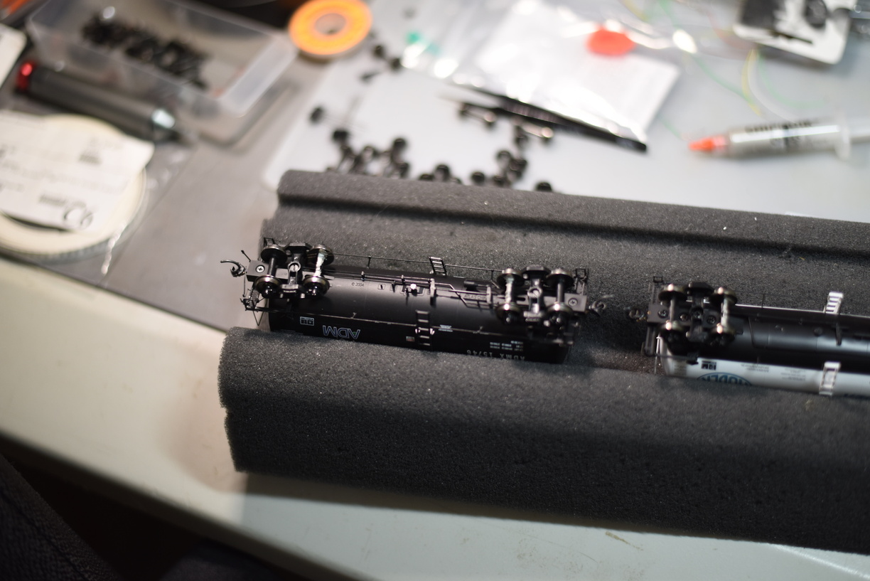
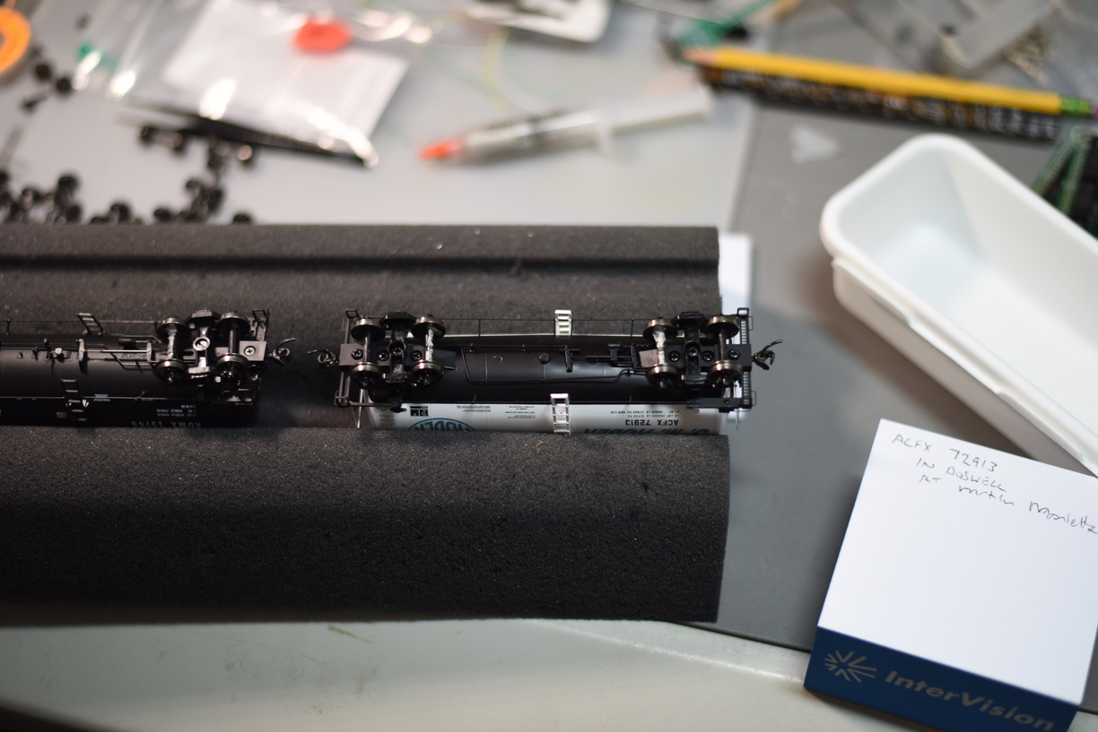
As an alternative, especially for cars that the factor axles are plastic, while the wheels themselves are metal, I glue the resistor in the middle of the axle, and then connect each side to the wheel with conductive paint.

It seems that tank cars are a consistent issue with being incompatible with the Intermountain option.

I have been checking the tank cars and also spotting any without Kadee couplers installed, so I grab them for the coupler replacement, and take the opportunity to handle the resistor wheelset issue.


The paint does take a bit to try, so doing this can tie up the foam cradle for a day.

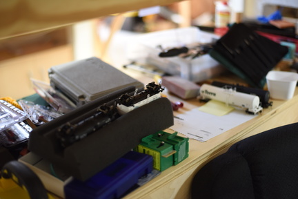
Cradle off the bench so I can do something else.


Friday, February 9, 2024

Dwarfs in Glen Allen

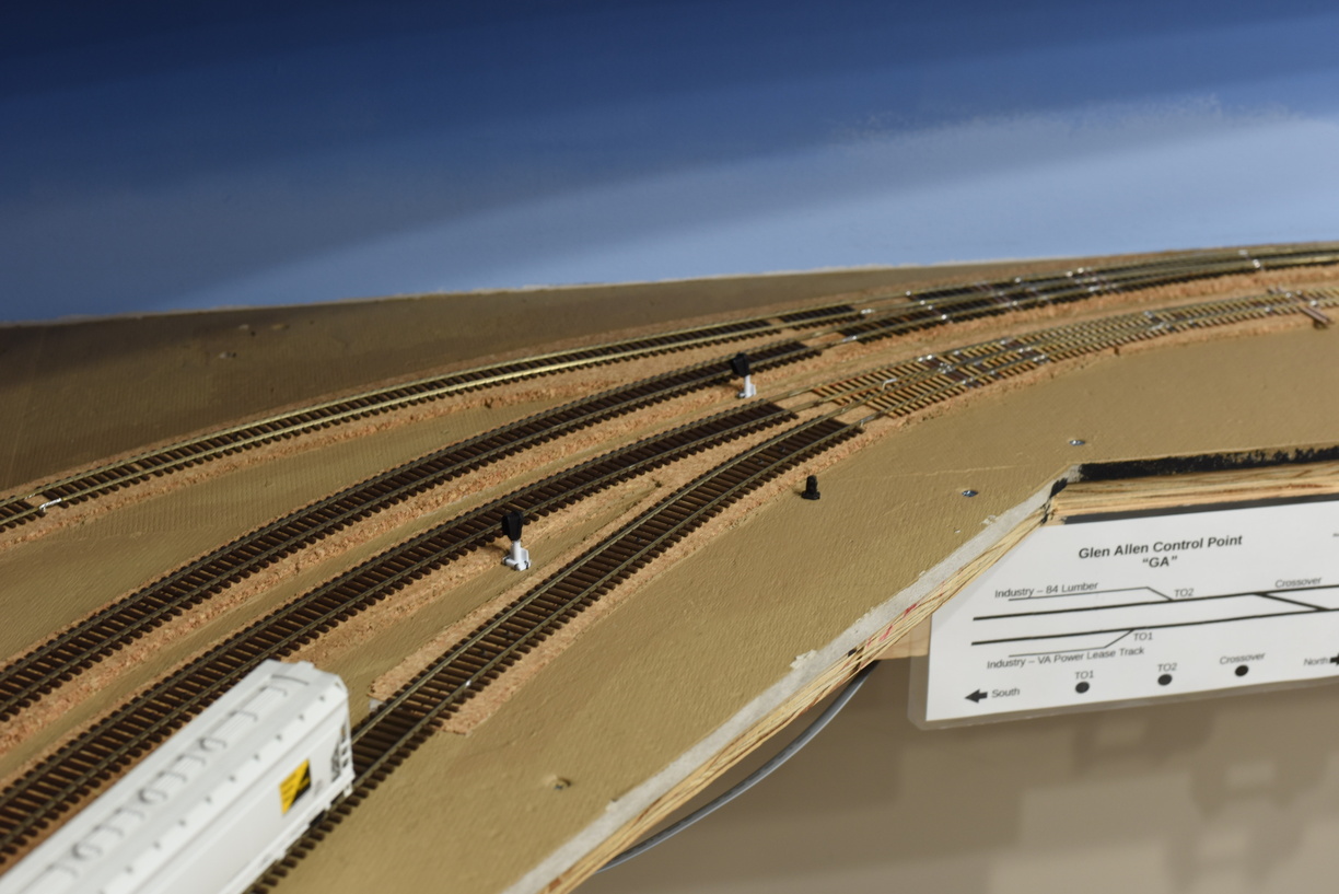
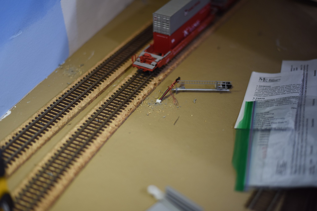
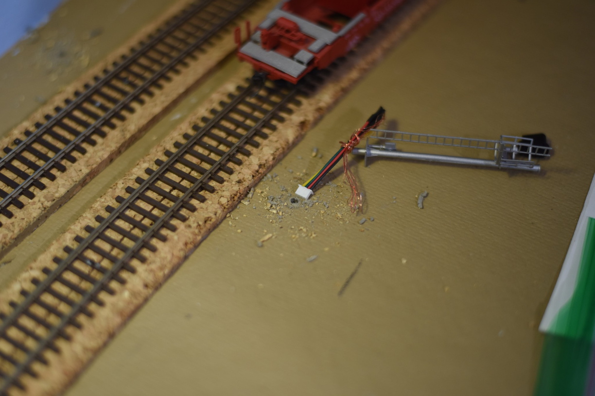
 Built two dwarfs, using Atlas heads; used one Tomar head.

These signals are controlled by a Nucleo, so the signal head driver is a combo of a logical signal head inside JMRI, and a Nucleo DevKit under the layout.


Wednesday, January 31, 2024

Signal Reworking

One of the outcomes when you operate is learning what changes need to be made to the layout to make operations smoother, more realistic, etc.

The railroad is maturing, which is giving me a chance to go back and install signals in areas that haven't been a priority, or to rework an area where the original signal install isn't reflective of how that area should be setup.

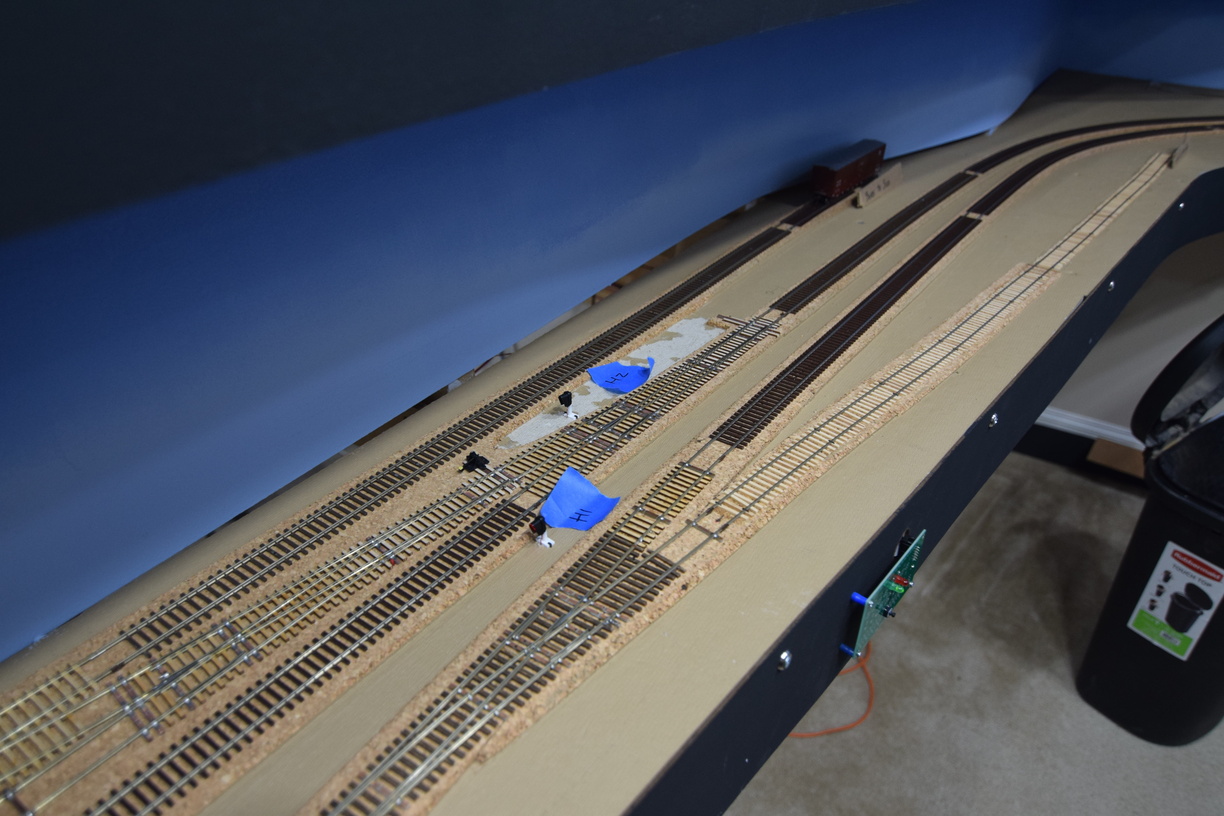
One of these locations that needed a net new install is the industrial turnout in Greendale, between the GN control point, and the Glen Allen (GA) control point.

There is a fair amount of industrial spots in this area, and both main lines have turnouts in place. I needed dwarf signals to protect these turnouts. One of them is currently manually thrown with a ground throw, so that will need to be modified to be thrown via a switch machine first, before signals get installed.

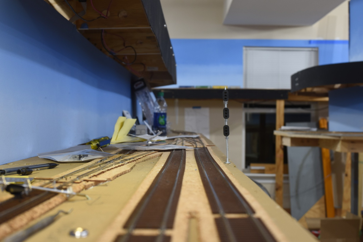
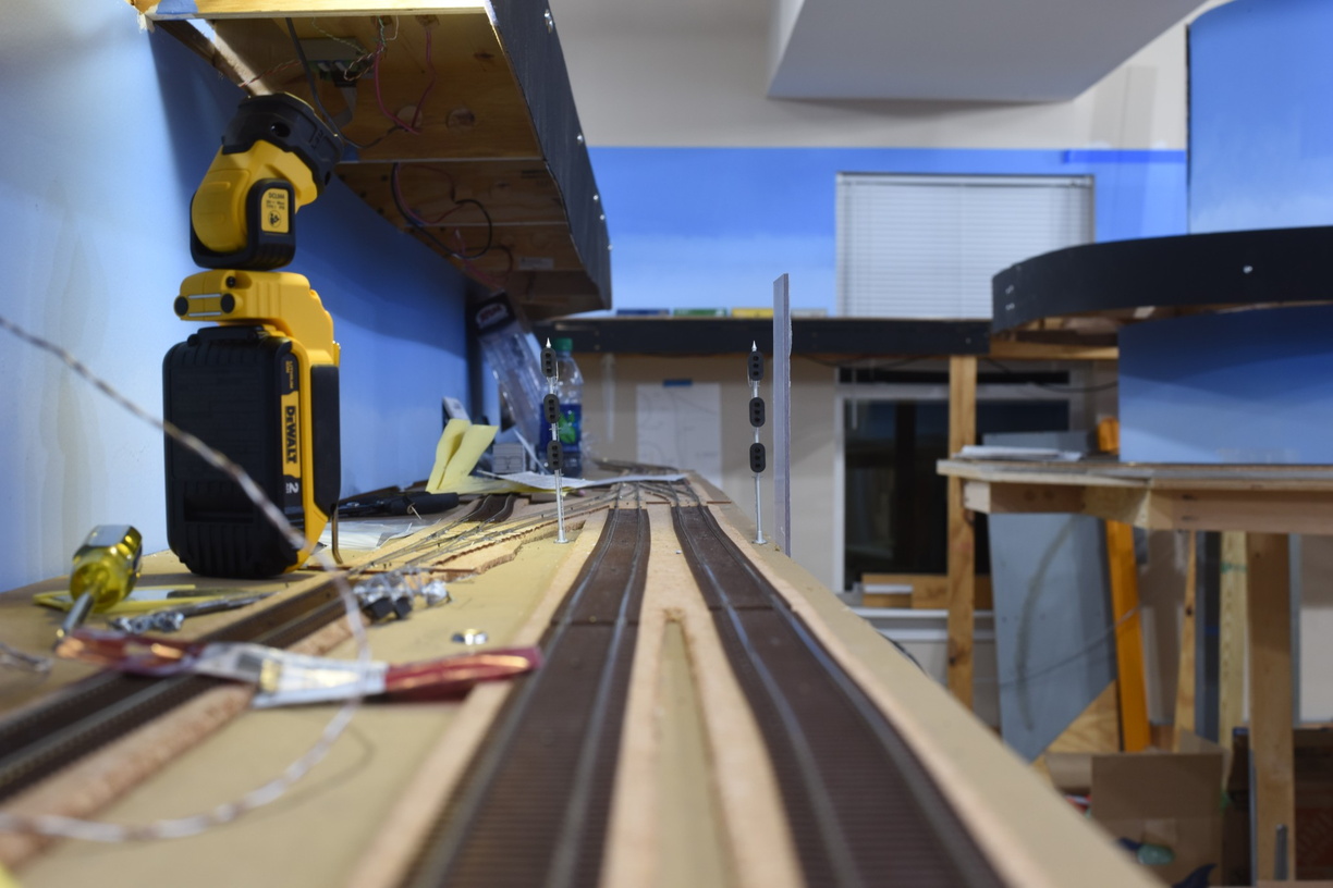
For the turnout that is currently controlled by a button (and will be controlled by the dispatcher in the future), I built a coulple of dwarfs and installed them.


I also took this opportunity to cut away a bunch of cork roadbed, and make the area look more realistic from a lineside perspective.

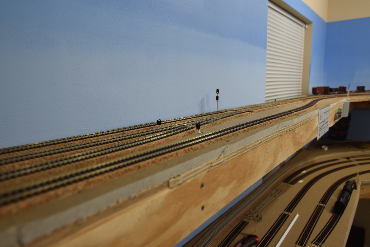
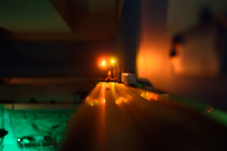
I had planned for a set of intermediate (repeater) signals between North Doswell and South Milford. This is matched up with Rutherglen on the prototype.

These are NJ International signals, with snow hoods. I will need to put something on the fascia in this area, since it can be hard to see these from the aisleway.


A spot that needed to be reworked is inside Doswell towards the north end.

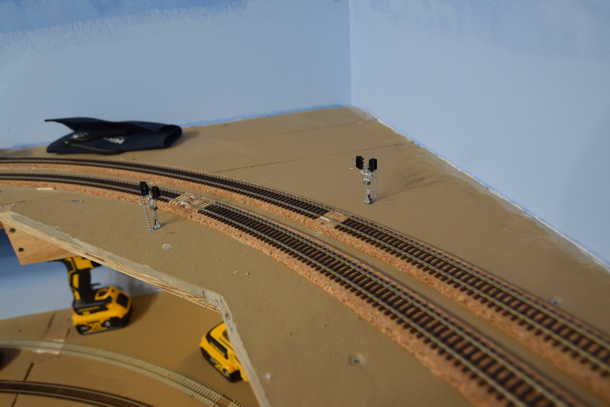
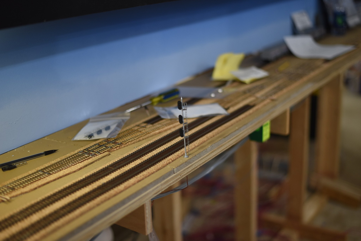
At the turnout that branches into track 4 from track 3, I originally had 2 high signals in this area. As I needed to only protect the turnout state, and not give advancement permission, I built and installed two dwarfs in their place.

The high signal in the background is for traffic that will be using the crossover, northbound, and getting clearance to enter the RF&P mainline


More pictures can be found in the gallery at richmond-terminal.org

Monday, January 8, 2024

Reworking Block Detection for Signals

The Richmond Terminal is a signaled railroad. The end goal is to have a functional CTC system in place like version 1 did. Version 1 used a virtual CTC panel based on the Union Switch and Signal components inside JMRI.

As we are still working on the operating scheme, I decided that an Automatic Block System (ABS) would make the most sense to implement at the start and once the operating scheme was solidified, I would pivot to setting up the CTC system.

ABS is currently running based on the LogixNG inside JMRI. As I have worked through the configuration, I realized that when I connected the track blocks, I erred.

The Richmond Terminal is a 2 track mainline railroad, which means there are crossover from one track to another. These crossovers are frequent. The railroad is just shy of 10 scale miles; there are 14 crossovers total.

I setup 1 detection section per crossover. This meant a couple of things - detection of the crossover section would prevent a dispatcher from throwing one under a train, but the detection state would not help me drop to red until a train moved through the crossover and hit the next block, and I could not test the crossover occupancy to set a signal aspect, either. 

Consider this example - a train is southbound on track 3, approaching a crossover. On track 2, a northbound train is moving through a crossover section, on a straight route. The crossover shows occupied, which is true for track 2, but NOT track 3.

This meant that I needed to go back and break apart the detection for each crossover and connect my blocks so that each component turnout of the crossover was detected separately.

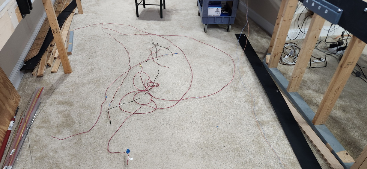
I took advantage of this and did some rationalization of my DCC bus as well.


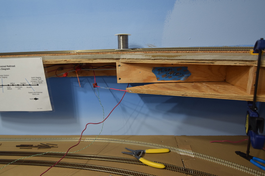
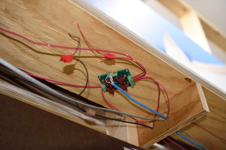
That's wire I pulled out from a part of 1 peninsula...

Here is a shot where I shortened bus wire and soldered new ends on. Had to clamp up a piece of plywood to give myself a working surface.


More pictures are in the gallery at richmond-terminal.org

Saturday, January 6, 2024

Protecting the fragile stuff

I daresay that almost every layout builder puts significant time and energy into their layout.

It's a downer when a scratchbuilt structure takes an inadvertent hit from a misplaced elbow or when an arm that is cleaning track, mashes a signal over.

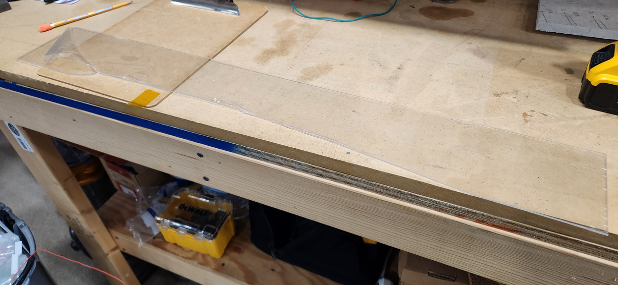
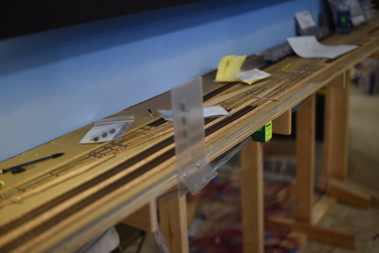
In an effort to protect these installations on the layout, I've used Acrylic sheets that I've cut to size as guards.

I'm still (re-) learning how to work with this stuff, and mistakes can happen.


Whoops. Needed a bunch more scribes on that one.

Saturday, April 1, 2023

March Operating Session

 March was the first session with the ABS signals running.

We found more than a few issues, but overall the system functioned.

This time, I did snap a few more photos than February, but I spent a bunch of time walking around and troubleshooting signals, so photos were a low priority.

Crew (from the book):

Bob S

Keith P

Dick M

Mike P

John V

Bryce

Scott


Engineer Bryce getting an Amtrak regional parked in the northern staging.

Bob (foreground) and Keith (background) running.

John has just left the North Acca Control Point on his way over the railroad with what looks like a local.

A few more shots can be found at richmond-terminal.org.

Another created in November, backdated post.

Tuesday, December 27, 2022

Resistor Wheelsets Again

Some time ago, I created a couple of batches of resistor wheelsets to be used on the freight car fleet to make sure that block detection worked fully. The blog post about the first phase of this is here if you are so inclined.

I used the Intermountain bulk wheelsets, 33" diameter for the first batch back then.

After using a bunch of them, I realized that some of the car fleet had a 36" wheel size, vs a 33" wheel size.

So, that means I needed to make some 36" wheels up with resistors.


I'm still using 10K 1/8W 0805 1206 SMD with the same procedure as before.

Jan 2024 Edit to fix this. I put together a new post about it, and wanted to link to the old posts. As I pulled the old posts to link, I realized I have had the resistor size wrong for years. Whoops!


Saturday, December 17, 2022

Rework Part I: Crossover and Signals at South Doswell

 As I mentioned in a previous post, a prototype crossover south of the diamond at Doswell was not selected for inclusion when the track was laid in that area of the railroad.

The reason for it being left out was the fact that I thought it wasn't needed based upon our operating designs at the time.

After a few operating sessions were ran, I realized that leaving it out was a mistake and it needed to be installed.

As shown in the post about the September work session here I built a crossover and a work crew installed it. What was left to me was installing the signals to make it a control point, along with the LCC components.

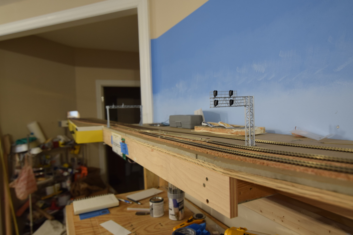
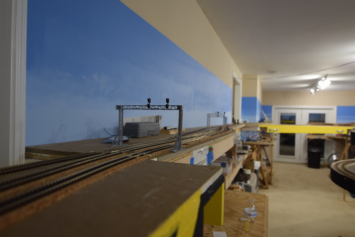
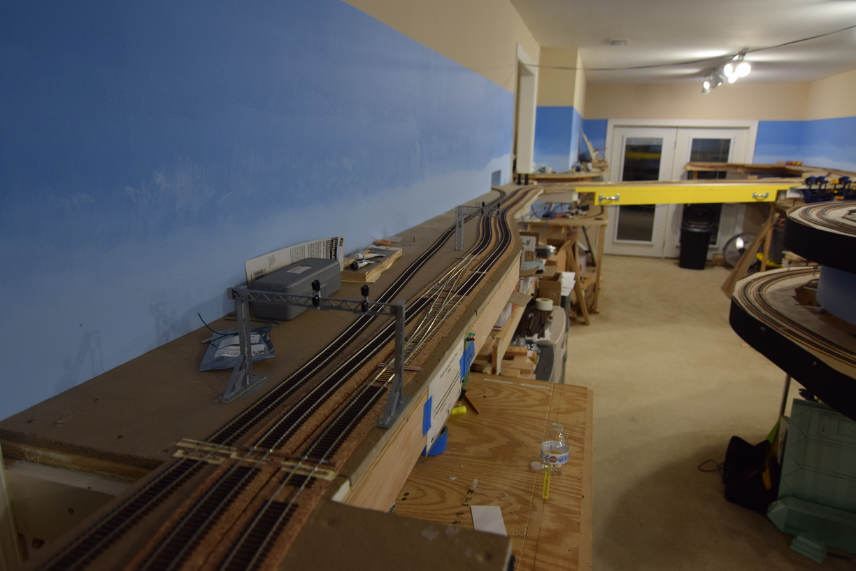
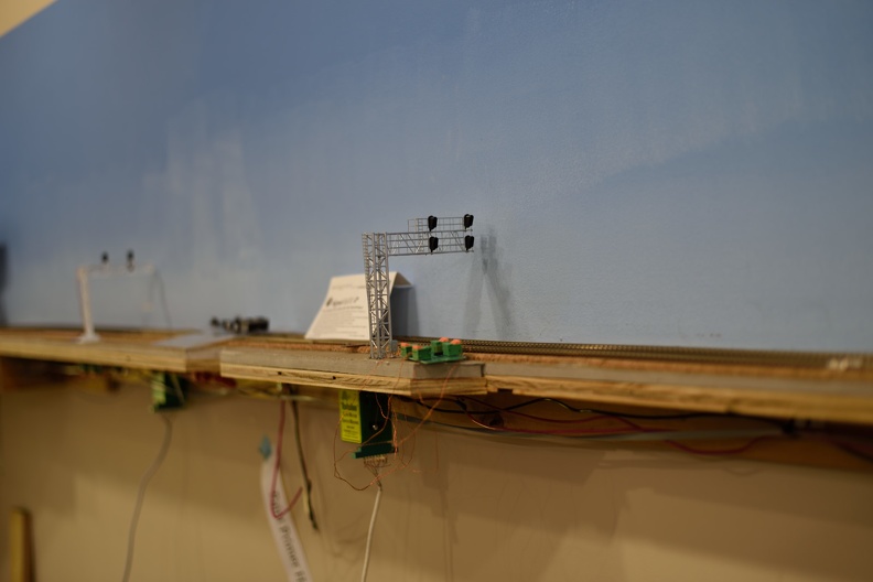
The Signals for SB traffic were pretty easy - a BLMA/Atlas modern, 2 track signal bridge was installed. As a side note, it has been tough to source the BLMA now Atlas signals due to various production/transporation delays and I ended up finding a hobby shop in Canada that has them in stock.


You will note in that picture, a track behind the signal mast. That is the last little bit of main line before you enter the north end staging yard; the wall cutout is just to the right by a few feet from our view here.

This meant that closer to the removable bridge that spans the main entrance to the layout, there isn't the space needed to install one of these type of signal bridges and make it hang the heads over the correct tracks.

To the rescue was my collection of polystyrene shapes and boards. I've scratch built a few other signals bridge on the layout, but this was my first to go over 3 tracks.

I used the Atlas/BLMA heads vs fooling with building my own, as that takes a way more time that just building the structure.


I also got my airbrush out and painted it with Vallejo's Model Air Steel color - really brought it up a few notches in looks from the bare white of the plastic. It was so impressive that I went and painted the other previously installed bridges across the layout.

We will close this post with a nice high angle aerial view of the control point.


More pictures are in the gallery at richmond-terminal.org

Wednesday, March 16, 2022

Signals at Greendale (GN Interlocking)

Years back while still operating the old railroad, I had plans to rebuild the set of cross overs just to the south of Acca, and install more prototypical signals versus the kitbashed signal bridges I had used.

The turnouts were installed in reverse order, in other words, the LH crossover was on the wrong side of the RH crossover. Compounding this, I used Atlas turnouts and one of them had a point that failed and stopped conducting power. Of course, this happened during an operating session.

The prototype had color light signals here for both tracks, using a 3 over 3 over 3 configuration. Unfortunately, the off the shelf signals available for HO are 3 over 3 at largest.

I found a custom signal builder that put together 3/3/3 signals for me and had him build me 6. By the time I got them, we had decided to sell and move, so I was pulling the layout down.

Fast forward and I finally got a chance to install these at the GN Interlocking after having them 6 or so years.


First one installed; this is for northbound traffic on track 2.


As you can imagine, with these installed right at the edge of the layout benchwork, they need protection from being bumped by random elbows and other body parts.

A piece of 1/8" acrylic was called to serve as a guard.


More pictures of this installation are on the gallery at the full website.

Tuesday, March 15, 2022

Thoughts on the Atlas (former BLMA) Signals

 Longtime readers and RTRR operators will remember that the railroad has a significant amount of signals in the overall physical plant of the railroad.

Version 1 was mostly a Tomar and NJ International with a smattering of BLMA color position signal heads kitbashed onto signals bridges.

Version 2 needs way more signals. The installations are a mix of BLMA, from old stock, Tomar, both from old stock, recovered from version 1 and new purchases, NJ International, new purchase, and some custom built 3 over 3 over 3 that look Tomar-ish.

When Atlas announced when they purchased BLMA that they intended to produce additional runs of the BLMA signals under their branding, I was super happy. It took way more time that I thought, but I was able to install some of the new signals on the railroad recently.

Atlas did produce new electronic options to drive the signals, which is something that wasn't present in the BLMA line up, but is not of any interest to me as I am using RR-Cirkits and OpenLCB project nodes on my LCC network to drive signals.


As part of that, Atlas had miniature QD connectors installed on the ends of the signal wiring.

Great idea, but the execution makes me wonder if anybody at Atlas actually tried to install these on a layout.


I'm going to go with, no, nobody did.

You can't get a 1/4" rectangular connector, through a 1/8" round hole...

I cut the connector off, since I can't use it anyway, but a bit of a disappointment.

Sunday, March 28, 2021

PCB Signal Mounting Update

I have designed PCB signals in various types, which I will be selling to others, but the genesis for this idea was the fact that I needed signals on the removable bridge sections of the layout.

I didn't want to risk expensive scale signals (at $25 to 48 each) on something that will get moved and placed at ground level, hence using signals that are just made out of circuit board.

Mounting them takes a 3/4" hole made with a forstner bit giving you a flat bottom hole.

The PCB is a bit smaller than 3/4, so you need a way to hold them in.


A piece of strip styrene and 2, #4 by 1/2" screws, and done!

Thursday, July 30, 2020

Thursday, May 28, 2020

Signal Update

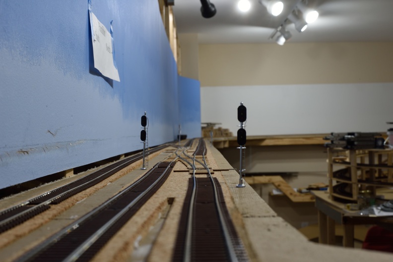
Signals on the upper level at Hamilton, XR, Milford and South Milford have been installed, lit and tested.

Signals at Doswell are mounted and testing/integration is coming.

Here's a shot of the crossover signals at the North Doswell Control Point to keep you interested.

Signal closet to the camera is a BLMA (now Atlas) modern cantilever bridge. In the background is one of my scratchbuilt creations as signal bridges can't be found at this time.


Thursday, April 16, 2020

Layout Control Options - The Main Problem

Layout control is a subject with an interesting history and there have been various systems and schemas that have ebbed and flowed in popularity over the years.

When I say layout control, I'm talking about an accessory bus or network and not something whose purpose is to allow you to make your engine move, so let's agree to call those train control for the purposes of these discussions.

Up until this point, most of the layout control systems were an additional use case driven by the need to connect throttles to the DCC command station, but all of these suffer from various architectural deficiencies. The sole exception to the offshoot situation that I can think of is C/MRI - Computer / Model Railroad Interface invented by Dr. Bruce Chubb. C/MRI has been around for a long time and has a pretty solid community around it; in fact many of the CTC systems that I know about use C/MRI as the infrastructure, whether the panel is driven from JMRI or a physical panel.

Various Arduino and other microprocessor based systems have been brewed and used, as model railroader are ingenious in their abilities to adapt things to model railroad use, going back to dyed sawdust as ground cover at the dawn of the hobby.

What these solutions have in common is a single, central problem.

Lack of Sustainability.

They are either the work of a single person (the Arduino schemes are examples) or company (Digitrax, C/MRI, Atlas, Walthers, etc) and in most cases, are closed and proprietary. So once the manufacturer stops making that or goes out of business, you either have to reverse engineer it and potentially run afoul of patents and the like or be willing to run it until it dies and throw it away to start over once you have enough failures that you can't live with it anymore. Similar story if the kids move out and you get that extra space to expand the pike but you can't buy that anymore.

Enter Layout Command Control.

LCC solves the problem, as it is a royalty free and license unencumbered standard that manufacturers are free to implement however they see fit. If a DIY type approach is more to your liking, the standards are available to you so you can work from that angle.

LCC is the adopted standards from the work of the OpenLCB group. OpenLCB was started from what I will call the ashes of the NMRANet project. If one wants to burn a day or three, you can search and find various electrons inconvenienced about NMRANet and how it went a bit pear shaped.

I first saw OpenLCB (still referred to as NMRANet) in 2012 at the Grand Rapids convention. I got an early DevKit, thinking that it would be something somewhat shake and bake. I was so so wrong.

Thankfully, that was then and this is now.

At this point, commercial hardware is available from RR-Cirkits and there are various open source DIY stuff too. I have a mix of RR-Cirkits and the Nucleo DevKit here on the layout. I personally laid out an expansion board for the Nucleo DevKit.

If you check out the main openlcb.org website you can see the general status. There is even a print book out about LCC!

I will put up more posts as I have time and inclination - this post has sat in a draft status for almost 2 years; its original post date was October 2018...

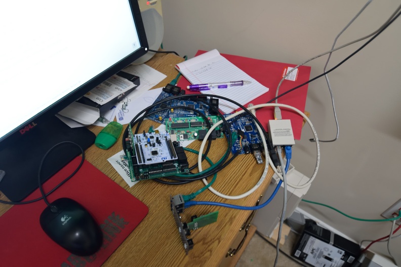
From 6 o'clock clockwise: (on edge) RR-Cirkits Tower-LCC, Nucleo DevKit (green and white PCB combo), Railstars IO (Blue PCB), LCC-Buffer. At center is a TCH Technology USB-Serial to CAN adapter that ended up having a fairly serious hardware bug..


Wednesday, April 8, 2020

Flash Traffic from Richmond Terminal Headquarters - Signal Activation

This evening at approximately 22:45 Eastern, 02:45 Zulu, the first signal on the Richmond Terminal Railroad was wired, tested, and activated on the control system.

This signal protects the siding and main track 2 for Southbound traffic at Milford, VA.

The Management, Officers and Employees of the Richmond Terminal are rightfully proud of this occasion and pray you lift a glass in celebration with them. (once you have gone off your current tour of duty, of course).

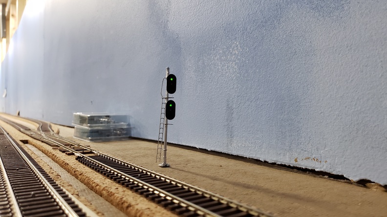
Tomar 3/3 US&S Signal installed alongside Main 2
In the background, you can see additional signals awaiting installation. The Signaling department will continue to work in the Milford area, including the South Milford control points before moving north towards XR, Hamilton and the Quantico CP.

Hamilton Signals Installed

Signals at the Hamilton Control Point have been installed and connected to the various driving boards.

I've got some additional updates around signals on the way so look for that content to post fairly soon. Being stuck at home is helping move the layout forward.

Here is my favorite shot:

Looking North here

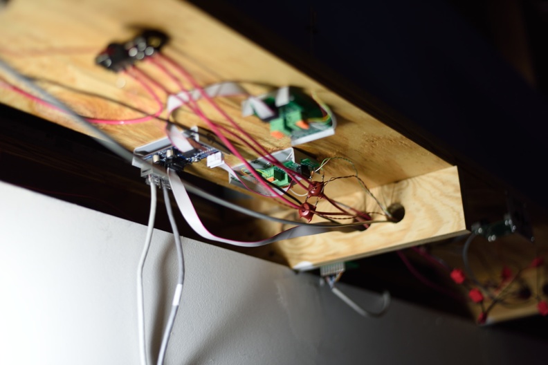
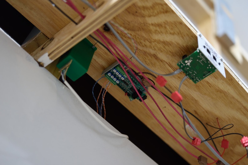
Under the layout to drive this stuff, I have RR-Cirkits Fan out boards (FOB) and a Signal-LCC board that drives the signals. The FOB lets me go from the fine 30 AWG gauge wire on the signals to the .1" square header pins.

Signal LCC at center left, FOBs center and center-right.

Working through the FOB lead me to put together an alternative circuit design to make it more economical, from both a money and space perspective. A future post coming about that as well.

Saturday, April 4, 2020

Block Detection

Quick block detection shot to share with my readers.


What you are seeing here at the center of the shot is a RR-Cirkits BOD-8 board. This is a board made to detect occupancy of up to 8 blocks, using current transformer coils that get placed on the DCC feeder for a rail of your choice. Also in the picture - Tortoise switch machine and Digitrax UP5 panel.

You can see that I use red for DCC Rail A and Black for DCC Rail B as the DCC bus and use 3M suitcase connectors to go from bus to feeder gang to feeder.

Per detected block, this is a probably the cheapest commercial way to do this. $35.40 is their direct NMRA pricing so that's $4.425 per block. A Digitrax BDL168 (which I used a bunch of on the previous railroad) runs about $120 for 16 blocks, which makes the math $7.50 a block there.

Once you figure out how many blocks even a smallish railroad requires, you try to figure out ways to maximize your ROI...

Tuesday, October 1, 2019

Block Detection Board, Version 1

Many folks know that I'm a bit handy with circuit design and board layout and try to make stuff easier on me and my fellow model railroaders.

As I've got a lot of screw terminal blocks from the Digitrax adapters I made years ago, I had to think of another way to use them up.

This is version 1. Version 2 is going to integrate the DCC block detector circuitry.


Friday, October 12, 2018

Detecting Trains for Signaling

Something that I didn't have on version 1 was detection of any rolling stock; only the engines were detected.

As you can imagine, this caused turnouts to get thrown under moving trains somewhat frequently.

The fix for this is resistor wheelsets. I bought resistors and conductive paint years ago to get it going and never actually sat down and got it done.

I sat in a clinic by Stephen Priest at KC2018 and he mentioned where he had done his entire fleet of cars (700+ ish) in 2 half Saturdays of work. He did an axle per car and that's what I am going to aim for as well.

That inspired me to give it a try.

The conductive paint pen didn't really work, as it has a finite lifespan and it was well over it so I had to take the pen apart and use a microbrush to get the paint onto the wheelsets.

I decided to standardize on Intermountain wheelsets, and in a spot of great luck, my Dad had a bunch of them from a buy his club did a while back.

Process - use a pair of tweezer to glue the resistor onto the side of the axle joint that is insulated with gel CA and wait. Then dab your conductive paint onto each contact side of the resistor and wait to dry. Test with your multimeter. Easy!

I'm going to buy another silver pen shortly when I'm ready to do more of them.

January 2024 Update to this post:
You can source a partial reel of 1000 of these resistors, for ~$15, even at current 2024 prices from Digikey or Mouser. I use Yageo brand resistors, but any manufacturer is fine. Get 1% or better tolerance. 10K Ohm, 1/8 watt.

You want 1206 size, so they aren't so hard to deal with. You could go bigger, 2010 size, if you are in O scale, I'd bet.

Reminder - gel type CA. Trying to use the thin stuff will be an exercise in frustration.

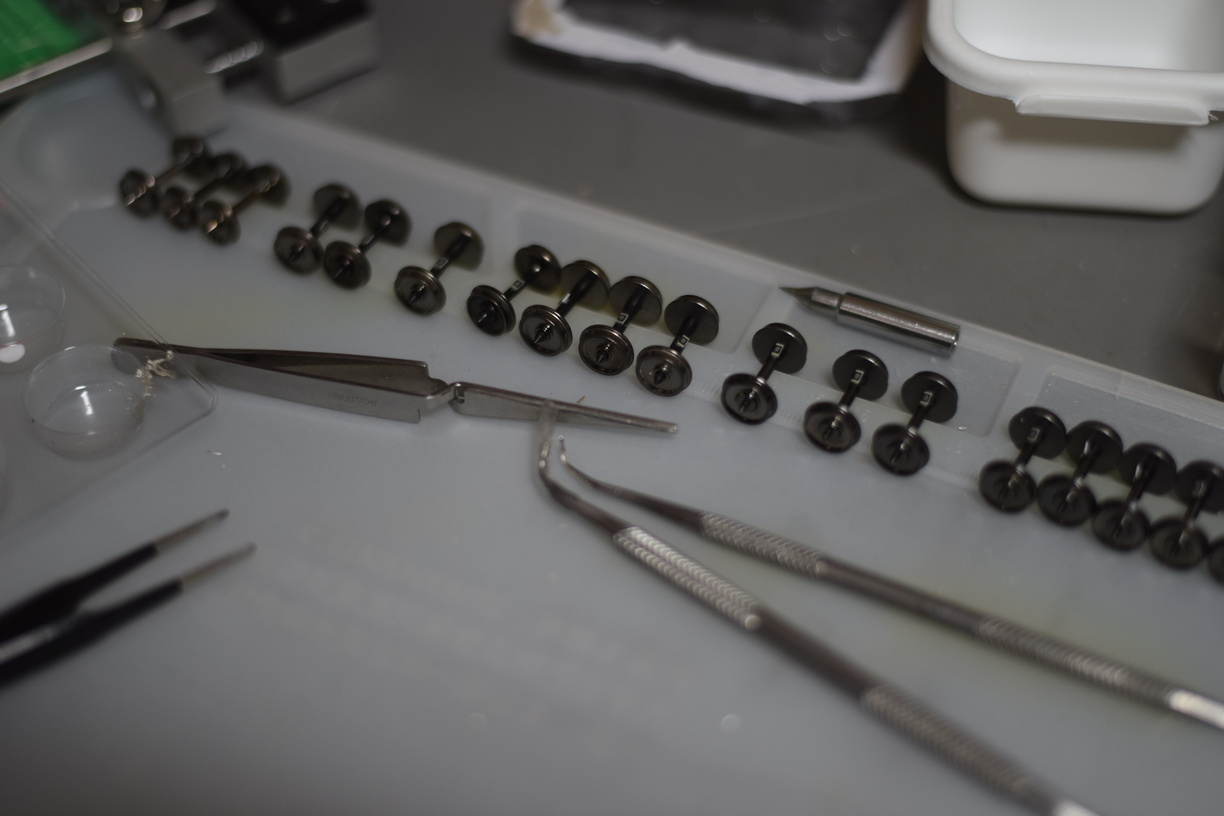
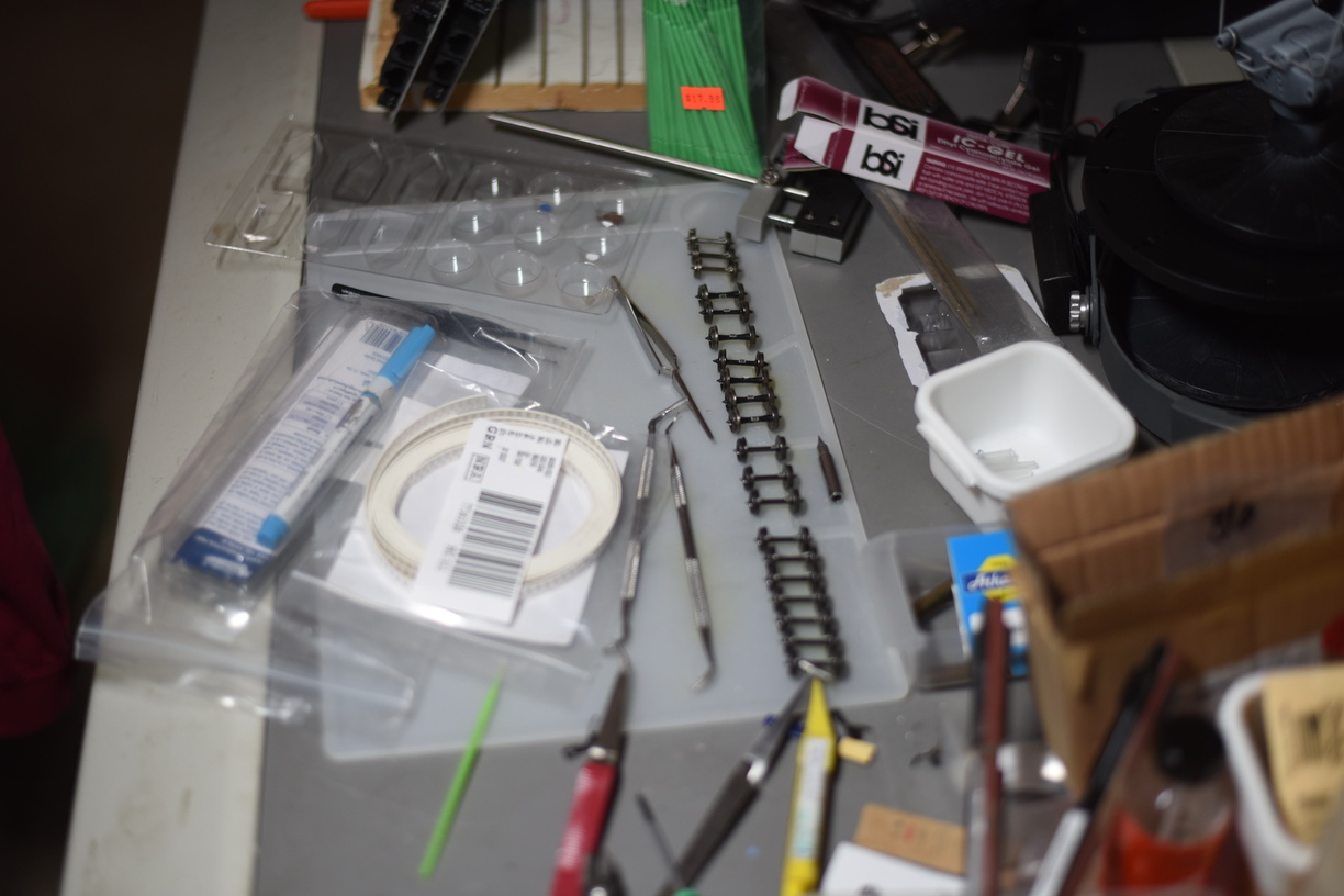
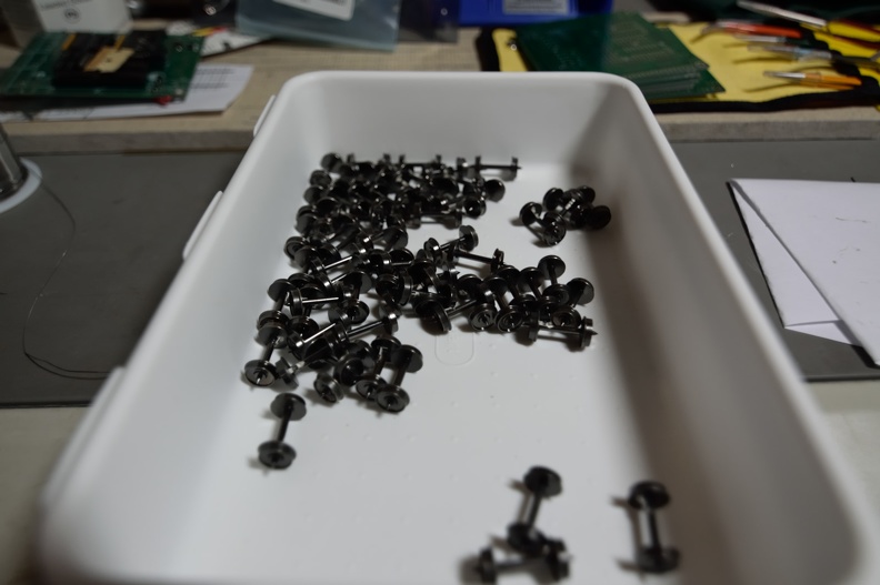
Done so far
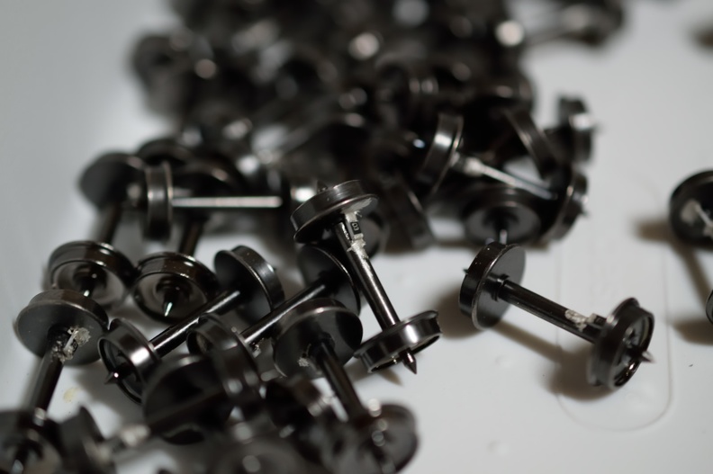
10K 1/8W 1206 size, if you are curious